In this article, we will discuss, an AC circuit that contains an inductor only. So let’s get started…
AC circuit containing an inductor only
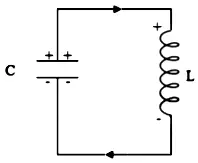
The below figure shows an inductor of inductance $L$ connected to a source of alternating EMF $\mathcal{E}$, which is given by $$\mathcal{E}=\mathcal{E_0}\sin\omega t\qquad … (1)$$

We assume that the inductor has negligible resistance. Thus the circuit is purely inductive a.c. circuit. As the alternating current flows through the inductor, a back emf $-L \frac{d t}{d t}$ is set up which opposes the applied emf.
$\therefore$ Net instantaneous emf $=E-L \frac{d l}{d t}$
But this emf must be zero because there is no resistance in the circuit.
| $$ \begin{aligned} \therefore \quad E{-L}\frac{d I}{d t} &=0 \text { or } E=L \cdot \frac{d I}{d t} \\ \text { or } \qquad \mathcal{E}_0 \sin \omega t &=L \cdot \frac{d I}{d t} \\ \text { or } \qquad d I &=\frac{\mathcal{E}_0}{L} \sin \omega t \cdot d t \\ \text { Integrating, } \quad\int dl& = \int \frac{\mathcal{E}_0}{L} \cdot \sin \omega t \cdot d t \\ I &=-\frac{\mathcal{E}_0}{\omega L} \cos \omega t+\operatorname{constant} \end{aligned} $$ |
As the applied EMF is sinusoidal, we expect the current also to be sinusoidal. Thus the average current $I$ must be zero over a time period. Now the average of $\cos\omega t$ is zero over a time period, hence the integration constant in the above equation must be zero. Then
| \begin{aligned}I&=-\frac{\mathcal{E_0}}{\omega L}\cos\omega t = -I_0\cos\omega t\\&=-I_0\sin\left({\frac{\pi}{2}-\omega t}\right)\qquad \left[\therefore \cos\theta =\sin\left(\frac{\pi}{2}-\theta\right)\right]\\ \text{or}\quad I&= I_0\sin\left({\omega t-\frac{\pi}{2}}\right)\quad….(2) \qquad \left[\therefore \sin(-\theta) =-\sin\theta\right] \end{aligned} |
Where $\displaystyle{I_0=\frac{\mathcal{E_0}}{\omega L}=\text{the peak value of AC}}$
Read Also
- Phasor and phasor diagram class 12
- Derive an expression for the average or mean value of AC for half cycle
- Expression for the RMS value of alternating current for a full cycle
The phase relationship between $\mathcal{E}$ and $I$
On comparing the equation (1) and (2). We find that the phase angle of current $I$ is $\frac{\pi}{2}$ rad less than that of $\mathcal{E}$.
Thus, in an inductive AC circuit, the voltage is ahead of the current in phase by $90^{\circ}$ or the current lags behind the voltage in phase by $90^{\circ}$. This means that the voltage $\mathcal{E}$ attains its maximum value $(\mathcal{E_0})$ a quarter of the cycle (time $\frac{T}{4}$)earlier than the current $I$, or the current attains its peak value $(I_0)$ a quarter of cycle later than the voltage $\mathcal{E}$. This phase relationship is shown graphically below.

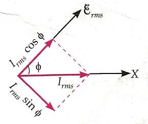
The left image shows the phasor diagram for an inductive AC circuit. The phasor $\overrightarrow{\mathcal{E}}$ makes an angle $\omega t$ with the x-axis in the anticlockwise direction. As the current lags behind the EMF in phase by $\frac{\pi}{2}$ rad, so the current phasor $\overrightarrow{I}$ makes an angle $\frac{\pi}{2}$ rad with the phase of $\overrightarrow{\mathcal{E}}$ in a clockwise direction.
What is Inductive reactance?
Inductive reactance Comparing equation $I_0=\mathcal{E}_0 / \omega L$ with the ohmic relation $I_0=E_0 / R$, we find that $\omega L$ play’s the same role here as the resistance $R$ in the resistive case. It is a measure of the effective resistance or opposition offered by the inductor to the flow of AC through it. Such a non-resistive opposition to the flow of current is called reactance. In this case, it is called inductive reactance and is denoted by $X_L$.
Inductive reactance is the property of an inductive coil or inductor that resists the change in alternating current (AC) through it and is similar to the opposition to direct current (DC) in a resistance.
$$
\therefore \quad X_L=\omega L=2 \pi fL
$$
where $f$ is the frequency of a.c. supply. The SI unit of inductive reactance is ohm $(\Omega)$
For AC, $X_L \propto f$
For DC, $f=0$, so $X_L=0$
Thus an inductor allows d.c. flow through it easily but opposes the flow of a.c. through it. Obviously,
$$I_{r m}=\frac{I_0}{\sqrt{2}}=\frac{\mathcal{E}0}{\omega L \sqrt{2}}=\frac{\mathcal{E}_{r m s}}{\omega L}=\frac{\mathcal{E}_{r m s}}{X_L}$$
Variation of $X_L$ with frequency
As $X_L\propto f$, so the graph of $X_L$ versus $f$ is a straight line with a positive slope. As $f$ increases, $X_L$ also increases.

Read Also
- AC circuit containing resistor only, class 12
- Representation of AC current and voltage by phasor diagram
Frequently Asked Questions – FAQs
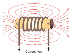
What is an inductor?
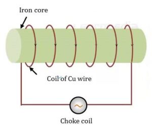
An inductor is a passive electrical component that opposes sudden changes in current. Inductors are also known as coils or chokes. The electrical symbol for an inductor is L.
What is inductive reactance?
Inductive reactance is the property of an inductive coil or inductor that resists the change in alternating current (AC) through it and is similar to the opposition to direct current (DC) in a resistance
What is the formula for inductive reactance?
Inductive reactance can be given by $X_L=\omega L=2 \pi fL$
Is it possible to have a pure inductor?
The circuit which contains only inductance (L) and not any other quantities like resistance and capacitance in the circuit is called a Pure inductive circuit. In this type of circuit, the current lags behind the voltage by an angle of 90 degrees.
What effect does an inductor have on an AC circuit?
The effect of an inductor in a circuit is to oppose changes in current through it by developing a voltage across it proportional to the rate of change of the current.
Stay tuned with Laws Of Nature for more useful and interesting content.