KIRCHHOFF’S CIRCUIT LAWS
INTRODUCTION
Do we know how can we find the value of electric current, voltage, and resistance by using ohm’s law? Ohm’s Law gives you a direct method to find these values. If you know the formula V = IR, then you can easily find your desired value.
We can apply ohm’s law in any circuit but it works well for simple circuits. As the circuit starts being complex then using ohm’s Law becomes time-wasting and confusing because it follows long procedures and working rules. So it is not a good idea to apply ohm’s law in complex circuits to find the value of electric current and voltages.
So for the complex circuits, in 1845 two different rules or you can say laws were discovered by the German physicist Gustav Kirchhoff. These rules are called Kirchhoff’s rules or simply Kirchhoff’s laws.

Kirchhoff gives two equalities that deal with the electric current and potential difference (commonly known as voltage) in the lumped element model of electrical circuits.
The laws which were given by Kirchhoff are based on the conservation of electric charges and conservation of energy. How it is based on these conservations? we will see below.
His laws are the generalization of the work of Georg Ohm and preceded the work of James Clark Maxwell. After introducing these two equalities the viewing angle of electrical engineering has been changed completely. It helps engineers to study complex circuits more precisely, accurately, and deeply.
These two laws are widely used in electrical engineering and became the basis of network analysis.
So in this article, we are going to discuss Kirchhoff’s laws in detail. So stay tuned with us till the end. Let’s start…
Before going further let’s discuss some frequent terms which will be used in the explanation of Kirchhoff’s law.
- CIRCUIT – It is a closed conducting path through which electric current flows.
- PATH – A single line of connecting components and sources. See figure below: A-B-D-A and A-B-C-D-A are different paths in the circuit.
- NODE – It is the junction where two or more circuit elements are joined together. In other words, it is the point from which two or more branches emerge. It is denoted by dots. It is similar to a railways junction.

As you can see in the figure, the red dots denote the nodes in the circuit. Here A, B, C, and D are different nodes.

In this figure, you will see there are three different loops. The first loop is A-B-D-A (loop 1), the second loop is B-C-D-B (loop 2), and the third loop are A-B-C-D-A (loop 3).
KIRCHHOFF’S CURRENT LAW (KCL)

Kirchhoff’s current law (KCL) is also called Kirchhoff’s first rule or Kirchhoff’s junction rule or nodal rule or Kirchhoff’s point rule. This is a very important law that is based on the conservation of electric charges. [latexpage]
STATEMENT – for any node or junction in electrical circuit, the sum of the current that are entering into the node or junction is equal to the sum of the current which are leaving that node.$$\displaystyle{\sum I_{\text{entering}}=\sum I_{\text{leaving}}}$$ In other words we can say algebraic sum of all the currents meeting at the node is zero.
Mathematically, it is given as-
$${\displaystyle \sum _{k=1}^{n}{I}_{k}=0}$$ where n is the total number of branches with currents flowing towards or away from the node.
| Keep in mind that direction is very important in Kirchhoff’s laws, if the current is entering the node then it is taken as (+) or positive current but if is leaving or going away from the node then it is taken as (-) or negative current. |
WHY DOES IT FOLLOW CONSERVATION OF CHARGES?
See figure above – in the above figure current $I_1$ and $I_2$ are entering into the node so it will be taken as positive current. But $I_3$ and $I_4$ are leaving the node so it will be taken as negative current. We know that the algebraic sum of all the currents meeting at the node is zero, then-
$${I_1+I_2-I_3-I_4=0}$$
We know that rate of flow of electric charges gives electric current. We also know that electric charges can’t be created nor destroyed. It is a conserved quantity like momentum and mass.
DERIVATION FOR CURRENT LAW
Let’s considered the charge at any instant of time t, if $I$ current is entered into the junction or node then the total charges entered into the node is $It$. Let’s assume that when this current $I$ is about to leave the junction, it is further divided into three different branches, having current in each branch is $I_1$, $I_2$ and $I_3$.
So the amount of electric charges in each branch is given as $I_1t$, $I_2t$, and $I_3t$. So according to the conservation of electric charges, the sum of all the charges before entering is equal to the sum of all the charges after leaving, so mathematically –
$$It=I_1t+I_2t+I_3t$$
Canceling t from both sides we get:
$$I=I_1+I_2+I_3$$
So this result gives Kirchhoff’s current law. Thus, from this, we can say Kirchhoff’s current law is the outcome of the conservation of electric charges in any circuit.
KIRCHHOFF’S VOLTAGE LAW (KVL)

Kirchhoff’s voltage law (KVL) is also called Kirchhoff’s second law, Kirchhoff’s loop (or mesh) rule, or Kirchhoff’s voltage rule.
This is also a very important law that was given by Gustav Robert Kirchhoff. Both these laws are widely used in electrical engineering for circuit analysis. This law is based on the conservation of energy. We will discuss below, how is it based on the conversation of energy?
STATEMENT – Kirchhoff’s voltage rule states that the sum of the emf of the cells in any closed loop is equal to the sum of the potential drops in that loop.
In the above figure you will see three different resistors due to this there exists three different potential drops. So according to the kirchhoff’s voltage law, it is given as- $$\displaystyle{E=V_1+V_2+V_3}$$
Similarly to Kirchhoff’s current law, the generalized form of voltage law can be given as-
$${\displaystyle \sum _{k=1}^{n}V_{k}=0}$$
Here, n is the total number of voltages measured in the loop.
UNDERSTANDING VOLTAGE LAW
In this section, we will understand how can we apply Kirchhoff’s voltage law in any closed circuit?
| Keep in mind that sign convention is very important in Kirchhoff’s law whether it is current law or voltage law. We have seen the sign convection for the current law above.
But in the voltage law, the potential drops in an arm are taken as positive if the direction of the current in the arm is the same sense as it moves but if the direction of electric current in the arm is opposite to the sense as one move then the potential drops are taken as negative. We will clarify it more with the below analysis. |
Let’s take a closed-circuit A-B-C-D-A containing two cells $E_1$ and $E_2$ and five resistors having resistance $R_1, R_2, R_3, R_4$ and $R_5$. See figure below:

Consider the loop B-A-C-B, we have taken this loop in the direction of the current from the cell which is at point B (cell-1). Let $I_1$ be the current coming out from cell-1 from point B to A.
When this current flows from point A to C then we see that another cell is joined in this arm (say cell-2). In this arm current $I_3$ is flowing towards the negative terminal of cell-2. This $I_3$ current seems opposite to the direction of the current in the loop B-A-C-B. So we will take EMF of this cell $E_2$ and current $I_3$ as negative.
So the total EMF in the loop B-A-C-B is-
$$E_1+(-E_2)=E_1-E_2$$
Similarly total potential drops in this loop is given as-
\begin{align*}
&=I_1R_1+(-I_3R_3)+I_2R_2\\
&= I_1R_1-I_3R_3+I_2R_2
\end{align*}
So according to the voltage law – the sum of the emf of the cells in any closed loop is equal to the sum of the potential drops in that loop. So according to it, it is given as-
$$\boxed{E_1-E_2=I_1R_1-I_3R_3+I_2R_2}$$
So similarly for the second loop A-D-C-A, it is given as-
$$\boxed{E_2=I_4R_4+I_5R_5+I_3R_3}$$
WHY DOES IT FOLLOW THE CONSERVATION OF ENERGY?
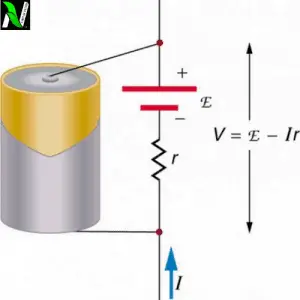
It is said that Kirchhoff’s voltage law is based on the conservation of energy. But how is it? Let’s find out… We know that work is done by the source EMF on the electric charge to maintain the flow of electric current in the circuit. See the figure below:
When work is done on the charged particles by the cell then it gains electrical energy but as it passes through various passive components such as resistors or loads then due to resistance, this electrical energy is converted into heat energy and released out. We know that energy can’t be created nor destroyed.
So let’s take Eq as the electrical energy, which is gained by the cell of EMF E. When these charged particles having electrical energy Eq, pass through three resistors then this energy is released in the form of heat due to their resistance is $V_1q, V_2q$, and $V_3q$.
So according to the theory of indestructibility of energy, the energy gained is equal to the energy lost. We can’t destroy energy by any means. So, we can write it as follows –
| $$\text{energy gained} = \text{energy lost}$$
$$\displaystyle{\sum E_{\text{gained}}=\sum E_{\text{lost}}}$$ |
$$Eq= V_1q + V_2q +V_3q$$
Cancelling q from both sides, we get-
$$E= V_1+ V_2+V_3$$
This result is nothing but Kirchhoff’s second law.
LIMITATIONS OF KIRCHHOFF’S LAWS
Kirchhoff’s circuit laws are not 100% accurate. It has some limitations also. Some limitations of Kirchhoff’s Law are given below:
- KCL is applicable only when the electric charge is constant in the circuit.
- KCL is applicable on the assumption that current flows only in conductors and wires. While in high-frequency circuits where parasitic capacitance can no longer be ignored. In such cases, Current can also flow in an open circuit because in these cases, conductors or wires are acting as transmission lines.
- KVL is applicable on the assumption that there is no fluctuating magnetic field linking the closed loop. While in presence of changing magnetic field in a high frequency but short-wavelength AC circuit, the electric field is not a conservative vector field. So, the electric field cannot be the gradient of any potential and the line integral of the electric field around the loop is not zero, this directly contradicts KVL. So in this situation voltage law can not be applicable.
- KCL assumes that the propagation of the electric field is instantaneous in the circuit. But it is not true every time. If your circuit is very long as thousands of kilometers then the propagation of the electric field is not instantaneous. It will take some time to reach the other point. For example:

Assume you have a very long circuit in which the battery and switch are at the earth and a LED light connected to the circuit is at the moon. When you switch on the power supply then an electric field is generated into the circuit. This electric field applies force to the electrons to cause motion. The electrons which are nearer to the battery on the earth experience an electric force but on the other hand, electrons that are nearer to the LED, it doesn’t feel any electric force and didn’t start to move because there is always some delay in reaching the electric field at distant positions.

As you can see in the above animation, any change in the electric field is not traveling instantaneously from left to right end, it takes to travel. But KCL assumes that it happens instantaneously.
SOLVED EXAMPLES
1). Using Kirchhoff”s rule, calculate the potential difference across the 8Ω resistance in the given circuit.  SOLUTION: we can redraw this circuit as follows  Let’s the current through the various arms of the network as shown in the figure above. Applying Kirchhoff”s voltage rule to the closed mesh A-D-C-B-A, we have- |
2). Determine the current in each branch of the following circuit.  SOLUTION: Redraw the circuit again indicating currents and their directions.  In a closed-circuit E-A-B-C-E, we have- |
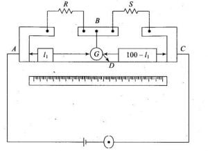
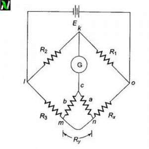
![Wheatstone bridge | working principle, construction and its derivation [class 12].](https://www.natureof3laws.co.in/storage/2021/06/wheatstone-bridge-300x240.jpg)