METER OR SLIDE WIRE BRIDGE
Today, we are going to discuss another type of electrical circuit, which helps measure the unknown resistance. If we know the three quantities then the fourth can be obtained by the balanced condition property. This is a variant of the Wheatstone bridge because its working principle is the same as the Wheatstone bridge.
We are talking about the meter bridge, this is one of the important topics of twelve-grade physics. So in this article, we are going to discuss everything about this variant. So let’s start…
WHAT IS A METER BRIDGE?
A metre bridge also called slide wire bridge is a simple form of potentiometer which are used in school science laboratories to demonstrate the principle of resistance.
A Meter bridge is a so-called meter bridge because a resistance wire of one meter is laid along the length of a meter rule.

In a meter bridge, the contact with the wire is made through a galvanometer by a slider or jockey. When the galvanometer reads zero current, then the ratio between the lengths of wire to the left and right side of the jockey’s contact point D is equal to the ratio between the values of a known and an unknown resistor in a parallel circuit.
CONSTRUCTION
The construction of the Meter bridge is quite simple. To construct a basic meter bridge, you need this equipment.
- Copper busbars of almost zero resistance
- Jockey
- One way key
- Leclanche Cell
- Constantan Wires
- Galvanometer
- Resistance Box
- Unknown Resistance Wire
Once you have gathered the required materials or pieces of equipment, you may construct your meter bridge. Follow these simple steps to set up a Meter bridge.
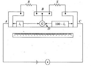
- Take two L shapes and a rectangular shape copper busbar and set it like as shown above.
- Join the one-meter constantan wire (sometimes called resistive wire) to the point A to C.
- Also, join a leclanche cell with one way key to the same point A and C. As shown above.
- Connect resistance box having resistance R to the first gap of copper busbars.
- Now connect unknown resistance S to the second gap of copper busbars.
- Make a jockey by connecting a galvanometer to it. Connect the positive terminal of the jockey to the rectangular copper busbars at point B and leave the negative terminal of the jockey free to slide over the resistive wire.
WORKING PRINCIPLE
Meter bridge works on the principle of Wheatstone bridge and the principle on which Wheatstone bridge works is –
When there is no current flowing through the galvanometer then the potential difference between the two midpoints (B and D) will be zero, and the galvanometer shows null deflection.
![Meter or slide wire bridge class 12 | working principle and construction. slide wire bridge class 12 Wheatstone bridge | working principle, construction and its derivation [class 12].](https://www.natureof3laws.co.in/storage/2021/06/1200px-Wheatstonebridge.svg-300x231.png)
So in this case –
\begin{align*} \frac{R_{2}}{R_{1}}&=\frac{R_{x}}{R_{3}}\\ \implies\qquad R_{x}&=\frac{R_{2}}{R_{1}}.R_{3} \end{align*}
We know that both known and unknown resistance ( first they are in series) is connected to points A and C (see figure above). And the resistive wire is also connected to the same point and A and C. It means they are connected to the parallel combination.
So due to they are connected to the parallel combination then the potential difference for both branches (resistors and resistive wire) will be the same.
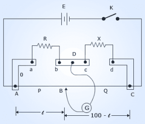
So, if we slide the jockey which is connected to the middle rectangular copper busbar at point D over the resistive wire then there will be a point on the resistive wire for which the reading of the galvanometer will be zero. See figure below:
Let’s assume B is the point on the resistive wire at which the galvanometer show null deflection, so $l$ is the first resistive length and $(100-l)$ is the second resistive length.
If the resistance wire of uniform cross-sectional area A has a constant resistivity ρ, it must have uniform resistance per unit length all over the resistive wire.
FINDING UNKNOWN RESISTANCE

From the balance equation of wheatstone bridge, we have –
\begin{align*} \frac{R_{2}}{R_{1}}&=\frac{R_{x}}{R_{3}}\\ \implies\qquad R_{x}&=\frac{R_{2}}{R_{1}}.R_{3} \end{align*}
Let’s take $R_2$ as $R$, $R_x$ as $X$, $R_1$ as $P$ $R_3$ as $Q$. When galvanometer shows null deflection then we have-
$$\frac{R}{P}=\frac{X}{Q}$$
We can also write it as follows:
$$
\displaystyle{
\frac{R}{\text{resistance across AB}}=\frac{X}{\text{resistance across BC}}}
$$
So, after writing resistance of each wire, we have-
$$
\frac{R}{\rho\frac{l}{A}}=\frac{X}{\rho\frac{(100-l)}{A}}
$$
Cancelling $\displaystyle{\frac{\rho}{A}}$ from both side of the denominator, we get-
\begin{align*}
\frac{R}{l}&=\frac{X}{(100-l)}\\
X&=\frac{R}{l}(100-l)
\end{align*}
So this is the required value of unknown resistance.
