In the previous article, we have derived an expression for magnetic force on the straight current-carrying conductor placed in a uniform magnetic field. But in this article, we will derive an expression for the magnetic force between the two parallel current-carrying wires. So let’s get started…[latexpage]
Magnetic force between the two parallel current carrying wires
When the current flows in same direction
| Note: magnetic force derived below is not in force per unit length. In order to find the force per unit length, divide the derived force by length $l$. |
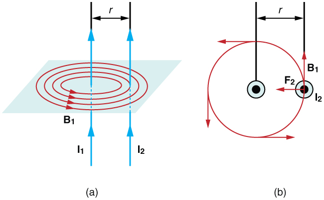
Let’s take two infinitely long straight parallel current carrying wires namely $l_1$ and $l_2$, seperated by the distance $\displaystyle{\mathbf{r}}$ such that the current $\displaystyle{\mathbf{I_1}}$ and $\displaystyle{\mathbf{I_2}}$ are flowing through them in the same direction, as shown in following figure.

We know that current-carrying wire produces a magnetic field in the form of concentric circles around the wire. So following this statement, first wire $l_1$ will produce magnetic field $B_1$ and the second wire $l_2$ will produce magnetic field $B_2$. Due to these magnetic fields, each wire will experience magnetic forces on itself. Second wire $l_2$ will experience magnetic force $F_2$ due to magnetic field $B_1$ of the first wire $l_1$ and first wire will experience magnetic force $F_1$ due to magnetic field $B_2$ of the second wire.
As we know that that the first wire will create a magnetic field $B_1$, in the shape of circles concentric with the wire. At the place of the second wire, the magnetic field $B_1$ is on the page and has a magnitude. $$B_{1}=\frac{\mu_{0}I_{1}}{2\pi r} $$ Since the second wire carries a current, $I_2$ in upward direction. It will experience a magnetic force $F_2$ in the presence of the magnetic field $B_1$ that is directed towards the left, see figure above, and it direction can be determined from the right-hand rule. The magnetic force $F_2$ exerted on a section of length $l$ on the second wire can be given as-
\begin{equation*}\begin{aligned} F_{2}=I_{2}||\vec l\times\vec B_{1}||=I_{2}lB_{1}=\frac{\mu_{0}I_{2}I_{1}l}{2\pi r} \end{aligned}\end{equation*} Here, we used the fact that the angle between $\vec{l}$ and $\vec{B_1}$ is 90°. We also expect from Newton’s Third Law, that an equal and opposite force should be exerted on the first wire as well. As the matter of fact, the second wire will create a magnetic field $B_2$, that is out of the page at the location of the first wire, whose magnitude can be given as- \begin{equation*}\begin{aligned} B_{2}=\frac{\mu_{0}I_{2}}{2\pi r} \end{aligned}\end{equation*}
The magnetic field $B_2$ leads to the magnetic force $F_1$ on the first wire, that points to the right from the right hand rule. On the section of length $l$ on the first wire, the magnitude of magnetic force $F_1$ can be given as- \begin{equation*} \begin{aligned} F_{1}=I_{1}||\vec l\times\vec B_{2}||=I_{1}lB_{2}=\frac{\mu_{0}I_{1}I_{2}l}{2\pi r} \end{aligned}\end{equation*}
We see that $F_1$ and $F_2$ both have equal magnitude. It means, when two parallel straight current-carrying wire has the current in the same direction then they exert equal and opposite attractive forces on each other.
When the current flows in opposite directions
If the current in the two parallel straight current-carrying wire flows in the opposite direction then there will be no change in the magnitude of the magnetic force that they experienced due to their corresponding magnetic fields. Only the nature of the magnetic force changes. In the case of current in the same direction, the nature of magnetic force is attractive but if the current is in opposite directions, the nature of the magnetic force is repulsive.

Definition of one Ampere
The attractive force between the two parallel straight current-carrying wires forms the basis for defining the value of one Ampere in their SI unit of an electric current.
Till the year 2019, the one Ampere of an electric current is defined as “the constant current that if maintained in the two parallel straight wires of infinite length, of negligible cross-sectional area, which is placed at one meter apart in vacuum, will produce a magnetic force between this two-wire, equal to $2\times 10^{-7}\text{N}$ per meter of the length.

But recently, the definition of one Ampere has been updated. It is now defined in terms of Coulomb in such a way that the elementary charge has a numerical value of $e = 1.602176 634\times 10^{-19}\text{C}$ and the definition of one Ampere correspond to the coulomb per second.
Watch this video for more visual understanding.
Stay tuned with Laws Of Nature for more useful and interesting content.

