Transformers are electrical devices that are widely used to transfer electrical energy from one circuit to another. The primary function of a transformer is to change the voltage level of an alternating current (AC) power supply to suit the requirements of the load connected to it. They are essential components in the electrical distribution system, allowing the efficient transmission of electrical energy over long distances.
Transformers come in various sizes and designs, and their use spans a wide range of applications in various industries. Michael Faraday proposed the concept of a transformer in 1831, and it was carried on by many other prominent scientific scholars. However, the general purpose of using transformers was to maintain a balance between electricity generated at extremely high voltages and electricity consumed at extremely low voltages.
This article explores the fundamentals of transformer devices, their working principle, types, and applications. So let’s get started…
What is Transformer class 12?
Transformer definition: A transformer is an electrical device that is used to transfer electrical energy from one circuit to another by means of electromagnetic induction. It works on the principle of Faraday’s Law of Electromagnetic Induction, which states that a change in the magnetic field induces an electromotive force (EMF) in a nearby conductor.

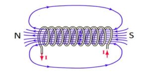
A transformer consists of two or more coils of wire wrapped around a common magnetic core. One of the coils, called the primary coil, is connected to the input voltage source, while the other coil, called the secondary coil, is connected to the load. When an AC voltage is applied to the primary coil, it produces a changing magnetic field, which induces an AC voltage in the secondary coil.
The voltage level in the secondary coil is determined by the ratio of the number of turns in the primary coil to the number of turns in the secondary coil. The transformer is a simple and efficient way to transfer electrical energy at different voltage levels without the need for any mechanical connection between the two circuits.
Construction of Transformer
A transformer is an electrical device that transfers electrical energy from one circuit to another through electromagnetic induction.

The construction of a transformer is quite simple and consists of a few essential components:
- Core: The core is the central part of the transformer that provides a path for the magnetic flux. It is made up of a high permeability material like silicon steel, laminated sheets, or ferrite.
- Windings: The windings are the conductive wires wrapped around the core to create a magnetic field. There are two types of windings in a transformer: primary and secondary. The primary winding is connected to the input voltage source, while the secondary winding is connected to the load.
- Insulation: Insulation is used to prevent the windings from touching each other or the core. It is typically made of an insulating material like paper, plastic, or varnish.
- Terminal: Terminals are the points where the input and output connections are made. They are typically located on the top of the transformer and can be screw terminals or lead wires.
The construction of a transformer involves the following steps:
- Core selection: The core material is chosen based on the required transformer specifications such as voltage, frequency, and power rating.
- Winding: The winding process involves wrapping the primary and secondary coils around the core. The number of turns in each coil depends on the desired voltage ratio of the transformer.
- Insulation: The windings are coated with insulation to prevent electrical arcing between the coils and the core.
- Assembly: The windings are then connected to the terminals, and the transformer is assembled.
- Testing: Finally, the transformer is tested to ensure it meets the required specifications and standards.
The construction of a transformer involves selecting the core material, winding the primary and secondary coils, insulating the coils, assembling the transformer, and testing it to ensure it meets the required specifications.
Different types of Transformer
There are several types of transformers, which can be broadly classified into the following categories:

- Step-up transformer: A step-up transformer is used to increase the voltage level of the AC power supply. It has more turns on the secondary coil than the primary coil.
- Step-down transformer: A step-down transformer is used to decrease the voltage level of the AC power supply. It has fewer turns on the secondary coil than the primary coil.
- Isolation transformer: An isolation transformer is used to provide electrical isolation between the primary and secondary circuits. It has the same number of turns on both the primary and secondary coils.
- Autotransformer: An autotransformer is a type of transformer that has a single winding with a tapped connection. It is used for voltage regulation and to provide different voltage levels.
- Instrument transformer: Instrument transformers are used in measurement and protection circuits. They include current transformers and potential transformers.
- Three-phase transformer: A three-phase transformer is used to supply power in three-phase electrical systems. It consists of three single-phase transformers connected together.
- Resonant transformer: A resonant transformer is used in high-frequency applications, such as in induction heating and fluorescent lighting.
- Distribution transformer: A distribution transformer is used to supply power to households and small businesses. It is usually mounted on a pole and is designed for high efficiency at low loads.
These are some of the most common types of transformers, and each has its specific application based on its design and features.
Classification criteria of different types of Transformer
The types of transformers can be based on several criteria such as:
- Voltage Level: Transformers can be classified into step-up transformers and step-down transformers based on the voltage level. A step-up transformer increases the voltage, while a step-down transformer decreases the voltage.
- Construction: Transformers can be classified as core-type and shell-type transformers based on the construction of the magnetic core. In a core-type transformer, the windings surround the core, while in a shell-type transformer, the core surrounds the windings.
- Application: Transformers can also be classified based on their application, such as instrument transformers, power transformers, distribution transformers, and isolation transformers.
- Frequency: Transformers can be classified based on frequency, such as low-frequency transformers and high-frequency transformers.
- Number of Phases: Transformers can be classified based on the number of phases, such as single-phase transformers, three-phase transformers, and polyphase transformers.
- Cooling System: Transformers can be classified based on the cooling system used, such as air-cooled transformers and oil-cooled transformers.
These are the most common criteria based on which transformers can be classified, and the classification helps in selecting the right transformer for a particular application.
Working principle of a Transformer class 12
The working principle of a transformer is based on the principle of electromagnetic induction. The transformer consists of two coils, a primary coil, and a secondary coil, wound around a common magnetic core. When an alternating current is applied to the primary coil, it produces a changing magnetic field around the core, which induces an electromotive force (EMF) in the secondary coil.

This EMF causes a current to flow in the secondary coil, which is proportional to the number of turns in the secondary coil. The ratio of the number of turns in the primary coil to the number of turns in the secondary coil determines the voltage transformation ratio.
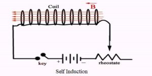
The transformer works only with AC voltage because it requires a changing magnetic field to induce EMF. When the primary voltage is increasing, the magnetic field expands and, when the voltage decreases, the magnetic field contracts. This process continues for each cycle of the AC voltage, and the magnetic field keeps changing, inducing an EMF in the secondary coil.
The transformer only works efficiently when both the primary and secondary coils are tightly coupled, which means that the magnetic flux produced by the primary coil should completely pass through the secondary coil. The coupling is achieved by placing both coils close to each other and winding them around a common magnetic core.
The transformer can be designed for step-up or step-down voltage transformation, based on the number of turns on the primary and secondary coils.
A transformer works on the principle of electromagnetic induction and is used to transfer electrical energy from one circuit to another at a different voltage level without any physical contact between the circuits. It is an efficient and reliable way to transmit electrical power over long distances with minimum energy losses.
Theory of Transformation class 12
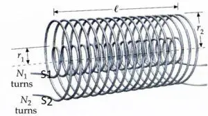
Consider the situation when no load is connected to the secondary, i.e., its terminals are open. Let $N_1$ and $N_2$ be the number of turns in the primary and secondary respectively. Then
Induced emf in the primary coil, $\quad \varepsilon_1=-N_1 \frac{d \phi}{d t}$
Induced emf in the secondary coil, $\varepsilon_2=-N_2 \frac{d \phi}{d t}$
where $\phi$ is the magnetic flux linked with each turn of the primary or secondary at any instant. Thus
$$
\frac{\varepsilon_2}{\varepsilon_1}=\frac{N_2}{N_1}
$$
Let $\varepsilon$ be the emf applied to the primary. By Lenz’s law, self-induced emf $\mathcal{E}1$ opposes $\varepsilon{\text {in }}$ the primary coil.
$$\therefore \text{Resultant emf in the primary}=\varepsilon-\varepsilon_1$$
This emf sends current $I_1$, through the primary coil of resistance $R$.
$$\therefore \quad \varepsilon-\varepsilon_1=R I_1$$
But $R$ is very small, so the term $R I_1$ can be neglected.
Then $$\quad \varepsilon=\varepsilon_1$$
Thus $\varepsilon_1$ may be regarded as input emf and $\varepsilon_2$ as the output emf.
$$\frac{\varepsilon_2}{\varepsilon_1}=\frac{\text { Output emf }}{\text { Input emf }}=\frac{N_2}{N_1}$$
The ratio $N_2 / N_1$, of the number of turns in the secondary to that in the primary, is called the turns ratio of the transformer. It is also called the transformation ratio.
In a step-up transformer, $N_2>N_1$, i.e., the turns ratio is greater than 1 and therefore $\varepsilon_2>\varepsilon_1$. The output voltage is greater than the input voltage.
In a step-down transformer, $N_2<N_1$, i.e., the turns ratio is less than 1, and therefore $\varepsilon_2<\varepsilon_1$. The output voltage is less than the input voltage.
It may be noted that equation (1) has been derived by using the following three assumptions :
- The primary resistance and current are small.
- The same flux links both with the primary and secondary windings as the flux leakage from the core is negligibly small.
- The terminals of the secondary are open or the current taken from it is small.
Read Also
- LC oscillation class 12
- Expression for energy and average power stored in a pure capacitor
- Expression for energy and average power stored in an inductor
Current in the primary and secondary coil
Currents in primary and secondary: Assuming the transformer to be ideal one so that there are no energy losses, then
Input power $=$ Output power or $\varepsilon_1 I_1=\varepsilon_2 I_2$
where $I_1$ and $I_2$ are the currents in the primary and secondary, respectively.
Hence
$$
\frac{I_1}{I_2}=\frac{\varepsilon_2}{\varepsilon_1}=\frac{N_2}{N_1}
$$
Thus, a step-up transformer steps up the voltage but steps down the current exactly in the same ratio. Similarly, a step-down transformer steps down the voltage but steps up the current exactly in the same ratio.
The efficiency of a transformer is defined as
$$
\eta=\frac{\text { Power output }}{\text { Power input }} \times 100 \%
$$
The efficiency of real transformers is fairly high $(90-99 \%)$ though not $100 \%$.
Parts of a Single-phase Transformer
A single-phase transformer consists of several essential parts, including:
- Core: The core is a magnetic circuit that provides a path for the magnetic flux to flow between the primary and secondary coils. The core is typically made of laminated silicon steel to reduce eddy current losses.
- Primary Coil: The primary coil is the winding that is connected to the input voltage source, which creates the magnetic field in the core. The number of turns in the primary coil is selected based on the input voltage and the desired output voltage.
- Secondary Coil: The secondary coil is the winding that is connected to the load, which receives the induced voltage from the magnetic field. The number of turns in the secondary coil is selected based on the output voltage required.
- Insulation: Insulation is provided between the primary and secondary coils to prevent short-circuiting and ensure proper isolation of the two circuits.
- Terminal Blocks: Terminal blocks are used to connect the primary and secondary windings to the power supply and load.
- Tap Changer: The tap changer is an additional winding that allows the transformer’s output voltage to be varied by changing the number of turns on the secondary coil.
- Tank: The tank encloses the core and windings and provides protection and support for the transformer.
- Cooling System: The cooling system is used to dissipate the heat generated in the transformer core and windings. It may be air-cooled or oil-cooled, depending on the transformer’s size and rating.
These are the primary parts of a single-phase transformer, and each plays a crucial role in the transformer’s operation. The design and construction of the transformer depending on the specific application, such as power distribution, lighting, or control circuits.
What is Ideal Transformer?
Ideal Transformer Definition: An ideal transformer is a theoretical concept that represents a transformer with perfect properties and no losses. It is a simplified model that assumes that the transformer has no resistance, leakage inductance, or core losses.
This means that all the electrical energy entering the primary winding is entirely transferred to the secondary winding without any loss or dissipation. An ideal transformer can be used to calculate the output voltage and current for a given input voltage and current without considering any losses.
The ideal transformer model assumes that the transformer has a perfect coupling between the primary and secondary windings, and the magnetic flux produced by the primary coil passes entirely through the secondary coil. The ideal transformer also assumes that the magnetic flux is proportional to the applied voltage and inversely proportional to the frequency.
In practical applications, an ideal transformer is not possible as all transformers have losses, including resistance losses in the windings, core losses, and leakage inductance losses. However, the ideal transformer concept is useful for understanding the basic principles of transformer operation and for making theoretical calculations.
Real-world transformers can be designed and optimized to minimize losses and improve efficiency by reducing core and winding resistances, using better core materials, and improving the coupling between the primary and secondary windings.
EMF equation of a Transformer (Ideal) class 12
The EMF equation in a transformer is used to calculate the induced voltage in the secondary coil of a transformer based on the primary coil’s input voltage and the number of turns in both the primary and secondary coils.

The EMF equation can be written as follows:
$$\text{EMF (Secondary)} = \frac{N_s}{N_p}\times V_p$$
Where:
- EMF (Secondary) is the induced voltage in the secondary coil
- $N_s$ is the number of turns in the secondary coil
- $N_p$ is the number of turns in the primary coil
- $V_p$ is the input voltage to the primary coil
The above equation assumes an ideal transformer with no losses. In practice, transformers have losses, such as resistance losses in the windings, core losses, and leakage inductance losses, which can affect the actual voltage induced in the secondary coil.
The EMF equation in a transformer is essential in determining the output voltage of the transformer for a given input voltage and turns ratio. It also shows that the output voltage of the transformer can be increased or decreased by changing the number of turns in the secondary coil or the turn ratio between the primary and secondary coils.
Voltage Transformation Ratio of a Transformer
The voltage transformation ratio of a transformer is the ratio of the primary winding voltage to the secondary winding voltage. It is usually represented by the symbol “k”, where:
$$k = \frac{E_1}{ E_2}=\frac{N_1}{N_2}$$
Here, $E_1$ is the voltage across the primary winding, and $E_2$ is the voltage across the secondary winding. The voltage transformation ratio of a transformer is determined by the number of turns in the primary and secondary windings. $N_1$ is the number of turns in the primary coil and $N_2$ is the number of turns in the secondary coil.
For a step-up transformer, the voltage transformation ratio is greater than 1, which means that the secondary voltage is higher than the primary voltage. For a step-down transformer, the voltage transformation ratio is less than 1, which means that the secondary voltage is lower than the primary voltage.
The voltage transformation ratio is an important parameter of a transformer, as it determines the voltage level at the output of the transformer. It is used in the design and operation of electrical systems to ensure that the voltage levels are within safe and acceptable limits.
Efficiency of a Transformer
The efficiency of a transformer is the ratio of the output power to the input power. It represents the amount of power that is delivered to the load compared to the power that is consumed by the transformer itself.
The efficiency of a transformer is an important factor in the design and operation of electrical systems, as it affects the overall energy consumption and operating costs.
The efficiency of a transformer can be calculated using the following formula:
$$\text{Efficiency} = \frac{\text{Output power}}{\text{Input power}} \times 100\% $$
Where, the output power is the power delivered to the load, and input power is the power consumed by the transformer itself. Both of these values can be measured using instruments such as wattmeters and ammeters.
In practice, the efficiency of a transformer is affected by various factors such as the core material, winding resistance, and eddy current losses. Therefore, it is important to select the right transformer design and materials to achieve the desired efficiency. High-efficiency transformers are typically used in applications where energy consumption is a major concern, such as in power generation and distribution systems, industrial processes, and data centers.
Long-distance transmission of electric power

The most important application of transformers is in the transmission of electrical power from a power station to faraway areas where it is actually used. The following are the disadvantages of transmitting electrical power at low voltage :
- The large length of transmission cables has appreciable resistance. Hence a large amount of energy $\left(I^2 R t\right)$ will be lost as heat during transmission.
- Large voltage drop (IR) occurs along the line wire. Hence the voltage at the receiving station will be much smaller than that at the generating station.
- To carry large currents and to keep the resistance of transmission wires low, thick wires have to be used. The cost of installing thick wires will be extremely high.
Thus long-distance power transmission at low voltage and high current is neither efficient nor economical. If $I$ is the current in the cable, and $R$ is its resistance, the power wasted in the cable is $I^2 R$. The power loss can be reduced by reducing $I$ or $R$. The power supplied by the generator is given by $P=V I$, where $V$ is the voltage across its terminals. Since $I=P / V$, for a given amount of power $P$, the power loss is less if $I$ is less or $V$ is high.
In actual practice, as shown below a typical power station generates $1000 \mathrm{~kW}$ at 6600 volts. This voltage is first stepped up to 132000 volts before transmission. Transmission lines from different power stations in a region deliver power to a common regional pool, called the grid. From the grid, the power is fed to the cities at $33000 \mathrm{~V}$, the stepping down is done outside the city. Then again at a sub-station, the supply is stepped down to $6600 \mathrm{~V}$. For domestic purposes, the voltage is again stepped down to $220 \mathrm{~V}$.

Applications of Transformer class 12
There are various applications of the transformer, some of them are:
- Power distribution: Transformers are widely used in power distribution systems to step down the voltage from high to low for safe and efficient use in homes and businesses.
- Electrical appliances: Transformers are also used in electronic devices such as TVs, computers, and refrigerators, to reduce the voltage and current levels and make the devices safer to use.
- Industrial machinery: Transformers are used in many types of industrial machinery such as motors, generators, and welding equipment, to regulate the voltage and current flow.
- Lighting systems: Transformers are used in lighting systems to regulate the voltage and current to the bulbs, making them more efficient and longer lasting.
- Audio equipment: Audio equipment such as microphones and speakers use transformers to convert the electrical signal from one form to another, which makes the sound clearer and more precise.
- Medical equipment: Many medical devices such as X-ray machines and MRI scanners use transformers to regulate the voltage and current flow, making the equipment safer and more reliable.
- Telecommunications: Telecommunications systems such as telephone and internet networks use transformers to convert the signal from one form to another, allowing for clear and efficient communication.
Read Also
- Wattless current class 12
- Power factor class 12 – definition, and formula
- Power in an AC circuit: definition, and formula derivation
- Choke coil – principle, working, and construction, class 12
- Sharpness of Resonance: Q-Factor in LCR circuit, class 12
Different types of energy losses in Transformer, class 12
Transformers are devices that transfer electrical energy from one circuit to another through electromagnetic induction. However, during this process, some amount of energy is lost in the form of heat and other factors. Here are some common types of energy losses in transformers:
- Copper Losses: Copper losses occur due to the resistance of the copper wire used in the transformer windings. The amount of copper loss is directly proportional to the square of the current flowing through the winding and the resistance of the wire.
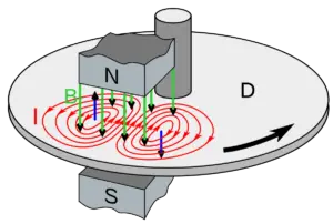
- Iron Losses: Iron losses, also known as core losses, occur due to the magnetization and demagnetization of the transformer core. This loss occurs as a result of the hysteresis effect and eddy currents in the core material, which generate heat.
- Stray Losses: Stray losses occur due to the leakage of magnetic flux from the core of the transformer. This leakage results in the generation of eddy currents in the surrounding conductive material, which causes energy loss.
- Dielectric Losses: Dielectric losses occur due to the energy dissipated as heat in the transformer’s insulation material. This type of loss occurs because the insulation materials are not perfect insulators and have a finite resistance to the flow of electric current.
- Load Losses: Load losses occur due to the resistive elements of the transformer’s winding that carry the load current. These losses are a combination of copper losses and eddy current losses.
- Humming Losses: “Humming loss,” which is also referred to as “mechanical loss” or “acoustic loss.” This type of loss occurs due to the vibration and sound produced by the transformer core when it is subjected to an alternating magnetic field. The magnetic field causes the transformer’s core to expand and contract rapidly, which creates vibrations and sound waves in the surrounding air. These vibrations and sound waves can cause energy loss in the form of heat and mechanical deformation
The energy losses in transformers can significantly affect their efficiency and performance. To minimize these losses, transformer designs and materials are optimized to reduce resistance, eddy current losses, and other sources of energy loss.
Solved Numericals on transformer, class 12
| 1.) A transformer has 600 turns of the primary winding and 20 turns of the secondary winding. Determine the secondary voltage if the secondary circuit is open and the primary voltage is 140 V. Solutuon: The voltage ratio of a transformer is equal to the ratio of the number of turns in the primary winding to the number of turns in the secondary winding. In this case, the voltage ratio is: $$\frac{V_p}{V_s} = \frac{N_p}{N_s}$$ where $V_p$ is the primary voltage, $V_s$ is the secondary voltage, $N_p$ is the number of turns in the primary winding, and $N_s$ is the number of turns in the secondary winding. Plugging in the given values, we get: $$\frac{140}{V_s} = \frac{600}{20}$$ Simplifying the equation, we get: $$V_s = \frac{(20 \times 140)}{ 600}$$ $$V_s = 4.67 V$$ Therefore, the secondary voltage when the secondary circuit opens is $4.67 V$. 2.) A transformer of 100% efficiency has 200 turns in the primary and 40000 turns in the secondary. it is connected to a 200 v main supply and secondary feeds to a 100 kΩ resistance. The potential difference per turn is: Solution: The potential difference per turn in a transformer is equal to the ratio of the input voltage to the number of turns in the primary winding. In this case, the potential difference per turn is: $$\frac{V_p}{N_p} = \frac{V_s}{N_s}$$ where $V_p$ is the primary voltage, $N_p$ is the number of turns in the primary winding, $V_s$ is the secondary voltage, and $N_s$ is the number of turns in the secondary winding. We know that the transformer has 100% efficiency, which means that the output power is equal to the input power. Therefore, we can use the following formula: $$P = V_p \times I_p = V_s \times I_s$$ where $P$ are the power, $I_p$ is the current in the primary winding, and Is is the current in the secondary winding. We are given that the secondary feeds a $100 k\Omega$ resistance. Therefore, the current in the secondary winding is: $$I_s = \frac{V_s }{ R }= \frac{V_s }{100000}$$ Substituting the values in the power equation, we get: \begin{aligned} V_p \times I_p &= V_s \times I_s \\ 200 \times I_p &= V_s \times \left(\frac{V_s }{ 100000}\right)\\ 200 \times I_p &= \frac{{V_s}^2 }{ 100000}\\ V_s &= 1000 \times \sqrt{20 I_p}\end{aligned} To find the potential difference per turn, we need to divide the secondary voltage by the number of turns in the secondary winding: \begin{aligned} \frac{V_s}{N_s}& = \frac{[1000 \times \sqrt{20 I_p}] }{ 40000}\\ \frac{V_s}{N_s} &= \frac{\sqrt{20 I_p}}{40} \end{aligned} Substituting the values of $V_p$ and $N_p$ from the problem statement: $$\frac{V_p}{N_p} = \frac{200}{200} = 1$$ Therefore, the potential difference per turn is: \begin{aligned}\frac{V_p}{N_p} &= \frac{V_s}{N_s}\\ 1& = \frac{\sqrt{20 I_p} }{ 40}\\ 40 &= \sqrt{20I_p}\\ I_p& = 80 \end{aligned} Substituting the value of $I_p$ in the equation for $V_s$: $$Vs = 1000 \times \sqrt{20I_p} = 1000 \times 40 = 40000 V$$ Finally, we can find the potential difference per turn as: $$\frac{V_s}{N_s} = \frac{40000 }{ 40000}= 1 \frac{V}{\text{turn}}$$ Therefore, the potential difference per turn in the transformer is $1 \frac{V}{\text{turn}}$. 3.) What kVA rating is required for a transformer that must handle a maximum load current of 8A with a secondary voltage of 2kV? Solution: The kVA (kilovolt-ampere) rating of a transformer can be calculated using the following formula: $$kVA = \frac{(I \times V) }{1000}$$ where $I$ is the maximum load current in amperes, $V$ is the secondary voltage in volts, and $1000$ is a constant used to convert the result to kilovolt-amperes. Plugging in the given values, we get: \begin{aligned}kVA& = \frac{(8 A \times 2000 V) }{1000}\\ kVA& = 16 kVA \end{aligned} Therefore, the $kVA$ rating required for the transformer to handle a maximum load current of $8A$ with a secondary voltage of $2kV$ is $16 kVA$. |
Frequently Asked Questions – FAQs
What is transformer and its work?
A transformer is a device that transfers electrical energy from one circuit to another by means of electromagnetic induction. It consists of two coils of wire, known as the primary and secondary, which are wound around a magnetic core.
When an alternating current is passed through the primary coil, it creates a changing magnetic field which induces a voltage in the secondary coil, thereby transferring energy between the two circuits.
Transformers are used in a wide variety of applications, including power transmission, voltage regulation, and electrical isolation. They are also found in many electronic devices, such as power supplies, audio amplifiers, and microwave ovens.
Is a transformer AC or DC?
A transformer is an AC (alternating current) device, which means it only works with alternating current. Transformers operate by creating a changing magnetic field around a coil of wire, which induces a voltage in another coil of wire.
This voltage is created only when there is a change in the magnetic field, which only occurs in an AC circuit where the current is constantly changing direction. DC (direct current) does not change direction, so it cannot be used to create the alternating magnetic field necessary for a transformer to work.
Why only AC is used in transformer?
Transformers work by creating a changing magnetic field in one coil of wire, which induces a voltage in another coil of wire. This voltage is created only when there is a change in the magnetic field, which only occurs in an AC (alternating current) circuit where the current is constantly changing direction.
If a direct current (DC) were to be used in a transformer, there would be no change in the magnetic field, and therefore, no voltage would be induced in the secondary coil. In other words, a transformer needs a changing magnetic field to function, and this can only be achieved with an AC current. So, only AC is used in transformers.
What is the basic principle of transformer?
The basic principle of a transformer is electromagnetic induction. When an alternating current (AC) flows through the primary coil of a transformer, it creates a changing magnetic field around the coil. This magnetic field then induces an alternating voltage in the secondary coil, which is connected to a load.
The voltage induced in the secondary coil is directly proportional to the number of turns in the secondary coil and the rate of change of the magnetic field. The transformer works on the principle of Faraday’s law of electromagnetic induction, which states that whenever there is a change in magnetic flux through a closed loop, an electromotive force (EMF) is induced in the loop.
In a transformer, the primary and secondary coils are wound around a common ferromagnetic core, which helps to concentrate the magnetic field and increase the efficiency of the transformer. The core also serves to provide a low reluctance path for the magnetic flux, reducing losses and improving the efficiency of the transformer.
What are 4 types of transformers?
There are several types of transformers, and they can be classified based on different criteria. The following are four common types of transformers based on their application:
1). Power Transformers: These are the most common type of transformers, and they are used for power distribution and transmission. They have a high power rating and are used to step up or step down the voltage in power systems.
2). Distribution Transformers: These transformers are used to distribute electrical power to homes and businesses. They have a lower power rating than power transformers and are used to step down the voltage from the primary distribution network to the secondary distribution network.
3). Isolation Transformers: These transformers are used to isolate electrical circuits from each other, providing electrical isolation and protection against electric shocks. They are commonly used in medical equipment, electronic devices, and other applications where safety is a concern.
4). Autotransformers: These transformers have only one winding, which acts as both the primary and secondary winding. They are used for voltage regulation and to provide a variable voltage output. Autotransformers are smaller and more efficient than conventional transformers, but they are not suitable for applications where electrical isolation is required.
What is transformer ratio?
The transformer ratio is the ratio of the number of turns in the primary winding to the number of turns in the secondary winding. The transformer ratio is a critical parameter that determines the voltage and current levels in the secondary winding relative to the primary winding.
For a step-up transformer, the ratio of the number of turns in the secondary winding to the number of turns in the primary winding is greater than one, which means that the voltage in the secondary winding is higher than the voltage in the primary winding.
For a step-down transformer, the ratio of the number of turns in the secondary winding to the number of turns in the primary winding is less than one, which means that the voltage in the secondary winding is lower than the voltage in the primary winding.
The transformer ratio can be calculated by dividing the number of turns in the primary winding by the number of turns in the secondary winding. For example, if a transformer has 1000 turns in the primary winding and 100 turns in the secondary winding, the transformer ratio is 10:1. This means that the voltage in the secondary winding will be one-tenth of the voltage in the primary winding.
Stay tuned with Laws Of Nature for more useful and interesting content.