In this present article, we will discuss the moving coil galvanometer, and its definition, types, working principle, construction, and applications, so let’s get started…
Introduction
The concept of galvanometer emerged from the observations made by Hans Christian Ørsted in 1820, that a magnetic compass needle deflected when it brought near a wire having electric current. Galvanometers were the first instruments used to detect and measure small amounts of current.
André-Marie Ampère, who gave mathematical expression to Ørsted’s discovery, named the instrument after the Italian electricity researcher Luigi Galvani, who in 1791 discovered the principle of the frog galvanoscope – that an electric current would make the legs of a dead frog jerk.
Galvanometers are very essential for the development of science and technology in many fields. For example, in the 1800s they enabled long-range communication through submarine cables, such as the earliest transatlantic telegraph cables, and were essential to discovering the electrical activity of the heart and brain, by their fine measurements of current. Today, the main type of galvanometer still in use is the D’Arsonval/Weston type.
What is moving coil galvanometer?
A moving coil galvanometer is an instrument that is used to detect the presence of electric currents. It is a sensitive electromagnetic device that can measure low currents even of the order of a few micro-amperes.
In starting galvanometers were uncalibrated, but improved versions, called ammeters, were calibrated and can measure the flow of current more precisely. Moving-coil galvanometers are mainly divided into two types:
- Suspended coil galvanometer
- Pivoted-coil or Weston galvanometer
Moving coil galvanometer construction and diagram

The construction of a moving coil galvanometer is not a big task. You can easily construct your galvanometer by getting little knowledge regarding it. For constructing a galvanometer you need the following major materials.
- Two permanent magnets
- A cylindrical soft iron core
- Moving coil
- Torsion head
- Suspension
- Mirror
Permanent magnets
We have discussed above that galvanometers are electromagnetic devices that detect the presence of electric current. If it does so that means electricity and magnetism are the main components of the galvanometers. In the galvanometers, for producing a static magnetic field we need a pair of permanent magnets. The magnetic field produced by it is used to apply torque on the rectangular current loop.
Soft cylindrical iron core
A soft cylindrical iron core is placed in the middle of the permanent magnets. It is enclosed within a frame of the rectangular current-carrying coil. It makes the magnetic field radial so that the angle between the plane of the coil and the magnetic lines of force remains zero at all times during the rotation of the coil. This iron core gives the less reluctance flux path and hence it provides a strong magnetic field for the coil to move in.
Moving coil
It is one of the main components of galvanometers. It is the current-carrying part of the galvanometer. It can be rectangular or circular and has several turns of fine copper wire. The coil is free to move about its vertical axis of symmetry between the poles of a permanent magnet. The moving coil is attached to a thin pointer that traverses a calibrated scale.
Torsion head
The moving coil is attached to a tiny torsion spring/head which pulls the coil and adjusts the pointer to the zero position. This means if there is no current flowing through the coil then the torsion head pulls the coil and pointer as well to the zero position.
Suspension
Suspension is the part that holds the moving coil in between the two magnetic poles. For holding the moving coil, both ends of the coil are attached to the two flat ribbon-like spirals called the spindle.
The spindle carries the electric current to the coil from the external source. The lower spindle (spiraled ribbon-like coil) where the torque effect due to rotation of the moving coil is small. The upper high suspension coil is made up of gold and copper in the form of a spiraled ribbon. The mechanical strength of both spindles is weak, so hold the galvanometer carefully without any heavy jerks. [latexpage]
Moving coil galvanometer working principle
As we know the current-carrying coil when placed in an external magnetic field experiences a torque. The angle through which the coil is deflected due to the effect of the magnetic torque is proportional to the magnitude of current in the coil. Therefore, a moving coil galvanometer works by deflecting a pointer in response to an electric current flowing through a coil in a constant external magnetic field.
Working of a moving coil galvanometer
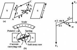
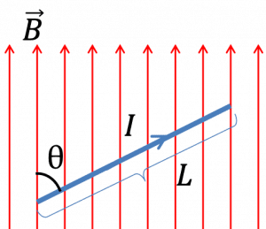
Let a current $I$ is flowing through the rectangular coil of turns $N$ and cross-sectional area $A$. When this coil is placed in a uniform radial magnetic field $B$, then the coil experiences a torque $\tau$.

Let’s first consider a single turn ABCD of the rectangular coil having a length $l$ and breadth $b$. This is suspended in a region of the magnetic field $B$ such that the plane of the coil is parallel to the magnetic field. Since the sides BC and DA are parallel to the direction of the magnetic field, they do not experience any effective force due to the magnetic field. But the sides AB and CD being perpendicular to the direction of the magnetic field experience an effective force $F$ given by $$F=lIB$$
Read Also
Torque experienced by the current-carrying loop in a uniform magnetic field
From Fleming’s left-hand rule, we can see that the forces on AD and BC are in opposite directions to each other. We know that when equal and opposite forces $F$ (called couple) acts on the coil, it produces a torque. This torque causes the coil to rotate about its vertical axis of the symmetry.
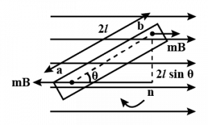
We know that torque is given as $\tau =\text{force}\times \text{ perpendicular distance between the forces}$ i.e $\tau=b\times F$ where $b$ is the perpendicular distance between the two forces and $F$ is the magnitude of the magnetic force.
Substitute the value of force $F$, we already know, after substituting we get- $$\tau =b\times lIB=IAB$$ where $lb$ is the area of the rectangular current loop and $(\sin\theta = 1)$ because the angle between the force and perpendicular distance is 90°. Hence the torque experienced by a current-carrying moving coil of turns $N$ is given as- $$\tau = NIAB$$
The magnetic torque thus produced causes the coil to rotate, so that the lower suspension (lower spindle) which is made up of phosphorus and bronze gets twisted. In turn, the lower spindle attached to the coil produces a counter torque or restoring torque kθ which results in a steady angular deflection.
Under the equilibrium condition, restoring torque $k\theta$ and magnetic torque is balanced, given as- $$k\theta=NIAB$$ Here $k$ is called the torsional constant of the spring (restoring couple per unit twist). The deflection or twist θ is measured as the value indicated on a scale by a pointer that is connected to the suspension wire. $$\theta=\frac{NIAB}{k}=\frac{NAB}{k}I$$ $$I=\frac{k}{NAB}\theta =G\theta$$ $$\frac{k}{NAB}=G$$ $$\therefore\; \theta \propto I$$ The quantity $\frac{k}{NAB}$ is a constant for a given galvanometer called galvanometer constant $(G)$. Hence, from the above equation, we can understand that the deflection that occurs in the galvanometer is directly proportional to the currents that are flowing through it.
Sensitivity of a moving coil galvanometer
The general definition of the sensitivity of a moving coil galvanometer is given as the ratio of the change in the deflection of the pointer of the galvanometer to the change in the current flowing in the coil. Mathematically, it is given as- $$S=\frac{d\theta}{dI}$$ The sensitivity of the galvanometer is said to be higher if it shows large deflection for a small change in the current. Moving coil galvanometer has two types of sensitivity.
- Current sensitivity
- Voltage sensitivity
Current sensitivity of a moving coil galvanometer
The current sensitivity of a moving coil galvanometer is the deflection per unit current flowing through it. It is given as- $$ I_S=\frac{\theta}{I}=\frac{NAB}{k}$$ It’s unit is rad/A or div/A.
Voltage sensitivity of a moving coil galvanometer
Voltage sensitivity of a moving coil galvanometer is the deflection per unit voltage. It is given as- $$V_S=\frac{\theta}{V}=\frac{NAB}{k}\frac{I}{V}$$ or $$\frac{NAB}{k}\times \frac{I}{IR}=\frac{NAB}{kR}$$ It’s unit is rad/V or div/V.
If you see the expression of voltage sensitivity and current sensitivity carefully then you will find that they have a close relationship between them. Voltage sensitivity = current sensitivity/R. Therefore, under the condition where R is constant then voltage sensitivity is directly proportional to the current sensitivity.
Read Also:
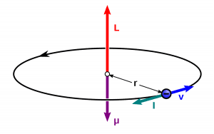
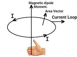
Magnetic moment of a revolving electron
Factors affecting sensitivity of a galvanometer
The sensitivity of a galvanometer is affected by various means. Some major factors are given below:
- Numbers of turns in the moving coil.
- Magnetic field strength
- Cross sectional area
- Magnitude of the couple per unit twist.
Figure of merit of the galvanometer
The figure of merit of a galvanometer is defined as the ratio of the full-scale deflection current and the number of graduations on the scale of the instrument. It is also the reciprocal of the current sensitivity of a galvanometer.
Conversion of a galvanometer to ammeter

To convert a galvanometer into an ammeter, its resistance needs to be lowered, so that maximum current can pass through it, and it can give an exact reading.
$$S=\left(\frac{I_g}{I-I_g}\right)G$$ where
- I = total current in the circuit
- G = resistance of the galvanometer
- S = resistance of the shunt (low resistance)
- $I_g$ = current through the galvanometer (full scale deflection current)
Conversion of a galvanometer to the Voltmeter

To convert a galvanometer into the Voltmeter, its resistance needs to be increased so that no potential drops occur across it because with resistance no current will pass through it. High resistance is connected in series with the galvanometer. $$R=\frac{V}{I_g}-G$$ where,
- V = potential difference across the terminal A and B
- $I_g$ current through the galvanometer (full scale deflection current)
- R = high resistance
- G = resistance of the galvanometer
Types of galvanometer
So far we have discussed D’Arsonval/Weston type moving coil galvanometer, but apart from this, there are more different types of galvanometers. Some galvanometers use a solid pointer on a scale to show measurements, while other very sensitive types of galvanometers use a miniature mirror and a beam of light to provide mechanical amplification of low-level signals. Some different types of galvanometers are given below:
| Galvanometric mechanisms are divided into moving magnet galvanometers and moving coil galvanometers. They are also divided into closed loop and open or resonant loop types galvanometer. |
- Tangent galvanometer
- Astatic galvanometer
- Mirror galvanometer
- Ballistic galvanometer
Tangent galvanometer

A tangent galvanometer is one of the first measuring devices to measure electrical current. It works by using a compass needle to compare a magnetic field created by the unknown current to the Earth’s magnetic field. It owes its name to its operating principle, the tangent law of magnetism, which states that the tangent of the angle formed by the compass needle is proportional to the ratio of the forces of the two perpendicular magnetic fields. It was first described by Johan Jacob Nervander in 1834.
A tangential galvanometer consists of a coil of insulated copper wire wrapped in a non-magnetic circular frame. The frame is mounted vertically on a horizontal base, which is provided with leveling screws. The coil can be rotated about a vertical axis passing through its center. Mounted horizontally in the center of a circular scale. It consists of a small and powerful magnetic needle that can be swiveled in the center of the coil. The magnetic needle can rotate freely in the horizontal plane. The circle scale is divided into four quadrants. Every quadrant. it is graduated from 0 ° to 90 °. A long, thin aluminum pointer is attached to the pen in the middle and at right angles. To avoid errors due to parallax, a flat mirror is attached under the compass needle.
During operation, the instrument is first rotated until the earth’s magnetic field, indicated by the compass needle, is parallel to the plane of the coil. Then the unknown current is applied to the coil. This creates a second magnetic field on the axis of the coil, perpendicular to the earth’s magnetic field. The compass needle responds to the vector sum of the two fields and deviates by an angle equal to the tangent of the ratio of the two fields. From the angle read by the compass scale, the current could be found from a table. [8] The power wires should be coiled into a small helix, like a pigtail, otherwise, the field due to the wire will affect the needle of the compass and you will get the wrong reading.
The galvanometer is oriented so that the plane of the coil is vertical and aligned parallel to the horizontal component $B_H$ of the earth’s magnetic field (i.e. parallel to the local “magnetic meridian”). When an electric current passes through the coil of the galvanometer, a second magnetic field is created B. In the center of the coil, where the needle of the compass is located, the field of the coil is perpendicular to the plane of the coil. The width of the coil field is: $${\displaystyle B={\mu _{0}nI \over 2r}\,}$$ From tangent law, B = BH tan θ, i.e $${\displaystyle {\mu _{0}nI \over 2r}=B_{H}\tan \theta \,}$$ or $${\displaystyle I=\left({\frac {2rB_{H}}{\mu _{0}n}}\right)\tan \theta \,}$$ or $$I=K\tan\theta$$ where K is called the Reduction Factor of the tangent galvanometer. But there is a problem with the tangent galvanometer, its resolution decreases with both high and low currents. The maximum resolution is achieved when the value of θ is 45° when the value of θ is near 0 ° or 90, a large percentage of the change in current will only move the needle a few degrees.
Astatic galvanometer
https://americanhistory.si.edu/
As with the tangential galvanometer, a static galvanometer does not use the earth’s magnetic field for measurement, so it does not need to be aligned relative to the earth’s field, which makes it easier to use. It was developed by Leopoldo Nobili in 1825, and consists of two magnetized needles that are arranged parallel to one another, but with reversed magnetic poles.
These needles are suspended from a single silk thread. The lower needle is located in a coil of vertical current measuring wire and is deflected by the magnetic field created by the flowing current, as in the tangent galvanometer above. The purpose of the second needle is to cancel the magnetic dipole moment of the first needle so that the suspended armature has no net magnetic dipole moment and thus it is not affected by the earth’s magnetic field. The rotation of the needle counteracts the torsional elasticity of the suspension rope, which is proportional to the angle.
Mirror galvanometer

To achieve greater sensitivity for detecting extremely low currents, the mirror galvanometer replaces the needle with a luminous mirror. It consists of horizontal magnets suspended from a thin fiber, inside a vertical coil of wire, with a mirror attached to the magnets. A beam of light reflected from the mirror falls on a graduated scale across the room, acting as a long, massless pointer. The mirror galvanometer was used as a receiver in the first transatlantic submarine telegraph cables in the 1850s, to detect extremely weak current pulses after their thousand-mile voyage under the Atlantic. In a device called an oscillograph, the moving beam of light is used to produce graphs of current against time by recording the measurements on photographic film. The string galvanometer is a type of mirror galvanometer so sensitive that it is used to perform the first ECG (electrocardiogram) of the electrical activity of the human heart.
Ballistic galvanometer

A ballistic galvanometer is a galvanometer that is sensitive to measure the amount of charge discharged through it. In contrast to a current measuring galvanometer, it is an integrator due to the long time constant of its reaction. The moving part has a large moment of inertia which gives it a sufficiently long period of oscillation to perform the integrated measurement. It can be of the moving coil or moving magnet type. It is usually a mirror galvanometer.
Applications of galvanometer
So the moving coil galvanometer is a highly sensitive device and therefore it is used to detect the presence of current in any given circuit. Apart from this, there are various applications of galvanometers in science and technology. Some applications of galvanometer are given below:
- To measure the presence of the current in the circuit or sometimes used to measure the small current in the order of micro-ampere.
- To measure the electric current in the circuit by adding a shunt (small resistance) parallel to the galvanometer.
- To measure the potential difference between the two terminal by adding a large resistance in series of the galvanometer.
- Mirror galvanometer are used as beam positioning or beam steering elements in laser scanning systems.
- Galvanometer are used in positioning and control systems.
- Closed-loop mirror galvanometers are also used in stereolithography, laser sintering, laser engraving, laser beam welding, laser TVs, laser displays and in imaging applications such as retinal scanning with Optical Coherence Tomography (OCT) and Scanning Laser Ophthalmoscopy (SLO).
- Open loop, or resonant mirror galvanometers, are used in laser-based bar-code scanners, printing machines, imaging applications, military applications and space systems.
- Tangent galvanometer can be used to measure the magnitude of the horizontal component of the geomagnetic field.
- Galvanometers can also been used as the display components of analog meters (e.g. light meters and VU meters).
Stay tuned with Laws Of Nature for more useful and interesting content.