Inductance is just another version of Lenz’s law. If anyone knows what is Lenz’s Law? then for him, understanding inductance becomes easier. In this article, we will talk about inductance – definition, formula, units, and dimensions, so without any delay let’s get started…
What is inductance?
Inductance: It is the tendency of an electrical conductor to resist a change in the electric current which are flowing through it.

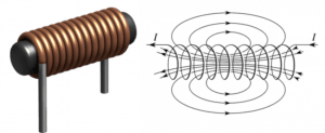
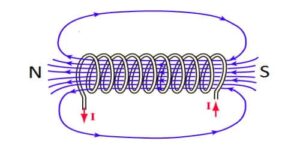
Whenever the electric current flows, it creates a magnetic field around the conductor. The strength of the field depends on the magnitude of the current and follows any current changes. From Faraday’s law of induction, if there is any change in magnetic field through a circuit induces an electromotive force (EMF) (voltage) in the conductors.
The process by which EMF is induced in the electrical conductor by changing the magnetic field linked to the conductor is known as electromagnetic induction. Lenz’s law states that the induced voltage by the changing current has the effect of resisting the change in current, and the voltage is called back EMF.
Inductance definition – Inductance is the ratio of the induced voltage to the rate of change of current causing it. It is a proportionality factor that depends on the geometry of circuit conductors and the magnetic permeability of nearby materials.
An electronic component designed to add inductance to a circuit is called an inductor. It typically consists of a coil or helix of wire. The inductance term was coined by Oliver Heaviside in 1886. The symbol ${\displaystyle L}$ for inductance is used, in honor of the physicist Heinrich Lenz.
Inductance is another version of Lenz’s law
Inductance is nothing but another version of Lenz’s law. Why am I saying this? let’s find out. Recall what Lenz’s law states?
Lenz’s law states that the direction of a current induced in a conductor by a changing magnetic field is such that the magnetic field produced by the induced current opposes the change in the original magnetic field.
This means, that in any conductor, changing magnetic field induces a current. The direction of this current is such that the magnetic field produced by this induced current opposes the change in the original magnetic field. Now let’s say the above statement in a different way.
Changing magnetic field induces a changing electric current in the conductor, the direction of this induced current is such that the secondary changing magnetic field produced by the induced current.
(Here, from Faraday’s law of electromagnetic induction, the secondary changing magnetic field produced by the induced current induces an electromotive force (EMF) to the conductor), and this EMF opposes the change in the original magnetic field, and what do these original changing magnetic fields induce? The original changing magnetic fields induce a current in the conductor. So now EMF opposes the change in current in the conductor.
It means EMF (induced by the secondary changing magnetic field) in the conductor opposes the change in current (current induced by the original changing magnetic field). In the case of inductance, induced EMF opposes the change in current in the conductor, and in the case of Lenz’s law, a secondary changing magnetic field due to induced current opposes the original changing magnetic field.
Inductance formula
A current flowing through a conductor creates a magnetic field around the conductor, which is described by Ampere’s circuit law. The total magnetic flux through a circuit ${\displaystyle \Phi }$ is equal to the product of the perpendicular component of the magnetic flux density and the surface area covered by the current path.
As the current varies, the magnetic flux ${\displaystyle \Phi }$ through the circuit changes. According to Faraday’s law of induction, any change in flux through a circuit induces an electromotive force (emf) or voltage ${\displaystyle {\mathcal {E}}}$ in the circuit that is proportional to the rate of change of the flow rate. $${\displaystyle {\mathcal {E}}(t)=-{\frac {\text{d}}{{\text{d}}t}}\,\Phi (t)}$$
The negative sign in the equation indicates that the induced voltage is in a direction that opposes the change in current that produced it; this is called Lenz’s law. Hence the potential is called EMF. As the current increases, the voltage at the end of the conductor where the current enters is positive, and at the end where it exits is negative, causing the current to tend to decrease.
As the current decreases, the voltage at the end where the current leaves the conductor is positive, tending to sustain the current. Self-inductance, usually just called inductance, ${\displaystyle L}$ is the ratio of the induced voltage to the rate of change of the current. $${\displaystyle v(t)=L\,{\frac {{\text{d}}i}{{\text{d}}t}}}$$ $$L=\frac{v(t)}{\frac{di}{dt}}$$
| Formula of inductance | $$L=\frac{v(t)}{\frac{di}{dt}}$$ |
| Formula of inductance | $$L=\frac{\Phi (i)}{i}$$ |
The inductance of a conductor depends on the geometry of the current path and the magnetic permeability of nearby materials; Ferromagnetic materials with higher permeability, such as e.g. Iron close to a conductor tend to increase the magnetic field and inductance.
Units of inductance
The unit of inductance in the SI system is Henry (H), named after the American scientist Joseph Henry, who represents the inductance that produces a voltage of one volt when the current is changing at a rate of one ampere per second.
| SI base units of inductance | kg⋅m2⋅s−2⋅A−2 |
|---|---|
| SI units of inductance | $\frac{\text{volt-sec}}{A}=\text{Henry}\;(H)$ |
Dimensional formula of inductance
Induced emf $|\varepsilon|=L\frac{dI}{dt}$
where $L$ is the self-inductance and $\frac{dI}{dIt}$ is the rate of change of current.
∴ Dimensional formula of $L=\frac{∣\varepsilon∣}{\frac{dI}{dt}}$
$$\begin{aligned}
&=\frac{[ML^{2}T^{−3}A^{−1}]}{[AT^{−1}]}\\
&=[ML^{2}A^{−2}T^{−2}]\end{aligned}$$
| Dimensional formula of inductance | M1·L2·T−2·A−2 |
What is an inductor?

An inductor is an electrical component consisting of a conductor shaped to increase magnetic flux to add inductance to a circuit. It usually consists of a wire wound into a coil or spiral. A coiled wire has a higher inductance than a straight wire of the same length because the magnetic field lines traverse the circuit several times and have several flux linkages. Inductance is proportional to the square of the number of turns in the coil, assuming full flux linkage.
Types of inductance
There are two types of inductance i.e. Self-inductance and Mutual inductance.
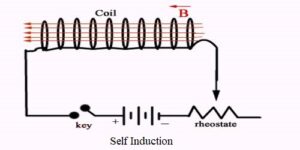
Self-inductance – Self-induction is defined as the phenomenon where a change in electrical current in a circuit creates an induced electromotive force in the same circuit.
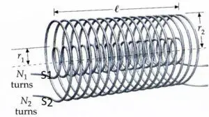
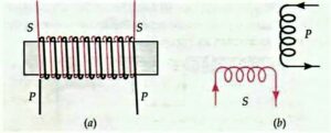
Mutual inductance – If there are multiple electric circuits located close to each other such that the magnetic field of one can pass through the other circuit, in this case, the circuits are said to be inductively coupled. Due to Faraday’s law of induction, a change in current in one circuit can cause a change in magnetic flux in another circuit, thus inducing a voltage in another circuit. In this case, the concept of inductance can be generalized by defining the term Mutual inductance.

Mutual inductance – Mutual inductance M(a,b) of the circuit (a) and circuit (b) is defined as the ratio of voltage induced in circuit ${\displaystyle a }$ to the rate of change of current in circuit ${\displaystyle b}$.
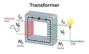
Mutual inductance is the basic working principle of transformers, motors, generators, and other electrical components that interact with another magnetic field.
How to increase the inductance of the coil?
The inductance of a coil can be increased by inserting a magnetic core made of ferromagnetic material into the center hole. The coil’s magnetic field magnetizes the core material and aligns its magnetic domains, and the core’s magnetic field adds to that of the coil, increasing the flux through the coil. This is called a ferromagnetic core inductor. A magnetic core can increase the inductance of the coil thousands of times.
Frequently Asked Questions – FAQs
What are inductance and induction?
When induction occurs in an electrical circuit and affects the flow of electricity it is called inductance
What is the value of 1 henry?
Reduced to base SI units, one henry is the equivalent of a one-kilogram meter squared per second squared per ampere squared (kg m 2 s -2 A -2 ).
What is electromagnetic induction?
The phenomenon in which the emf and hence the current is induced in the circuit by changing the magnetic field.
Define 1 Henry?
The self-inductance of the coil is equal to 1 Henry if 1 volt of emf is induced in a coil when the current through it changes at 1 ampere per second.
On what factors does inductance depend?
Factors that affect the inductance are
Number of Wire Turns in the Coil. The greater the number of turns of wire in the coil, the greater the inductance.
Coil Area: The greater the coil area, the greater the inductance.
Core Material
Coil Length
How can inductance be increased?
The inductance of a coil can be increased by inserting a magnetic core made of ferromagnetic material into the center hole, and by increasing the number of coils turns. we can also increase inductance by increasing the diameter of the coil or making the core longer.
Does inductance depend on frequency?
The inductance of an inductor is a constant and does not depend on frequency or on the current. The inductance value of an inductor depends on the construction of the conductor.