In this article, we will discuss an AC circuit that contains a resistor and inductor in series, so let’s get started…
AC circuit containing $L$ and $R$ in series
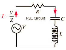
In the below figure, let’s consider a resistor $R$ and an inductor $L$ connected in series to a source of alternating EMF $\mathcal{E}$ that is given by $$\mathcal{E}=\mathcal{E_0}\sin\omega t$$

Let $I$ be the current through the series circuit at any instant, then
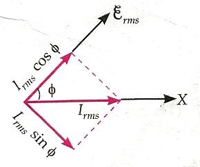
1). Voltage $\overrightarrow{V_R}=\overrightarrow{I}R$ across the resistance $R$ will be in phase with the current $\overrightarrow{I}$. So phasors $\overrightarrow{V_R}$ and $\overrightarrow{I}$ are in the same direction, as shown in the below figure. The amplitude of $\overrightarrow{V_R}$ is $${V_0}^R=I_0 R$$

2). Voltage $\vec{V}L=X_L \vec{I}$ across the inductance $L$ is ahead of current $\vec{I}$ in phase by $\pi / 2$ rad. So phasor $\vec{V}_{\mathrm{L}}$ lies $\pi / 2 \mathrm{rad}$ anticlockwise w.r.t. the phasor $\vec{I}$, It amplitude is
$$V_0{ }^L=I_0 X_L $$
where $X_L$ is the inductive reactance.
By the parallelogram law of vector addition,
$$\vec{V}_R+\vec{V}_L=\vec{\mathcal{E}}$$
Using the Pythagoras theorem, we get
| \begin{aligned} \mathcal{E_0}^2 &=\left(V_0^R\right)^2+\left(V_0^L\right)^2=\left(I_0 R\right)^2+\left(I_0 X_L\right)^2 \\ &=I_0^2\left(R^2+X_L^2\right) \\ I_0 &=\frac{\mathcal{E_0}}{\sqrt{R^2+X_L^2}} \end{aligned} |
Read Also
- AC circuit containing an inductor only
- AC circuit containing resistor only, class 12
- Representation of AC current and voltage by phasor diagram
Impedance of $L-R$ circuit
Clearly, $\sqrt{R^2+X_L^2}$ is the effective resistance of the series L.R-circuit which opposes or impedes the flow of a.c. through it. It is called its impedance and is denoted by $Z$. Thus
| $$Z=\sqrt{R^2+X_L^2}=\sqrt{R^2+\omega^2 L^2} \quad\left[\because X_L=\omega L\right]$$ |
The phase angle $\phi$ between the resultant voltage and current is given by
| \begin{aligned}\tan \phi=\frac{V_0^{L}}{V_0^R}&=\frac{I_0 X_L}{I_0 R}=\frac{X_L}{R}=\frac{\omega L}{R}\\ \text{Or}\quad \cos\phi =\frac{R}{Z}\end{aligned} |
It is obvious from the phasor diagram that the current lags behind the emf by phase angle $\phi$ so the instantaneous value of current is given by
$$\left.I=I_0 \sin (\omega t-\phi\right)$$
Stay tuned with Laws Of Nature for more useful interesting content.